Viewer Functions
DAIMIA Connector provides several powerful 3D functions that enable you to interact with and analyze your models more effectively.
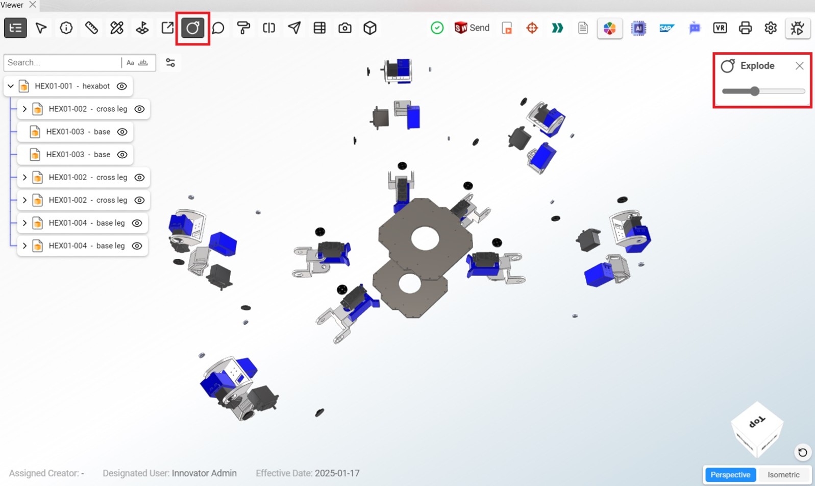
Exploding Assemblies
The Explode function separates components of an assembly to view individual parts more clearly. You can use this tool to get a better understanding of how the parts fit together.
3-Axis Sectioning
The 3-Axis Sectioning tool allows you to cut through the model along any of the three axes (X, Y, Z). This helps you view internal details of the model that are not visible from the outside.
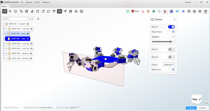
Sectioning In addition to the 3-axis sectioning, the Viewer allows for detailed section views along the X, Y, and Z planes, enabling in-depth inspection of internal structures.
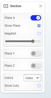
- Show Plane: Keeps the square with the section guide visible on the screen.
- Negated: Inverts the cut section.
- Show Cuts: Highlights the cut areas with color. The “Material” and “Index” options define the color. If “Material” is selected, the object appears in its original color (though this may not be easily distinguishable). With “Index,” different colors are assigned to each object.
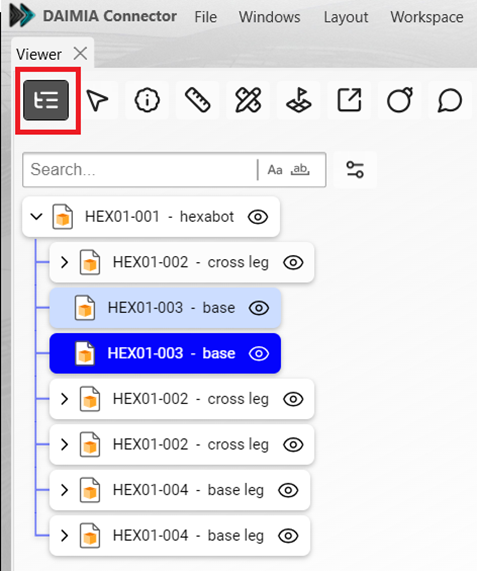
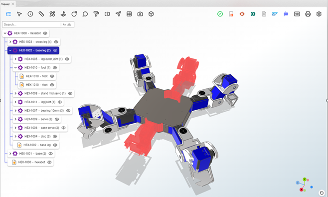
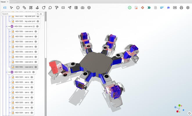
Product Tree Levels
The Product Tree Levels feature lets you explore different hierarchical levels of the product structure. You can navigate between parent and child components to view the full scope of the product assembly.
Search in Product Tree
The search tool within the Product Tree enables you to quickly find specific parts or assemblies by entering keywords or part numbers, improving navigation speed.
Hover Selection
Hover selection allows you to highlight and select components in both the Product Tree and the Viewer. This feature simplifies part identification and ensures seamless interaction between the Viewer and the product hierarchy.
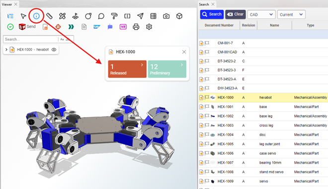
Summary
The Summary tool provides an overview of assemblies, including the number of parts, their types, and states. This feature is particularly useful for obtaining quick insights into the structure and current status of the assembly.
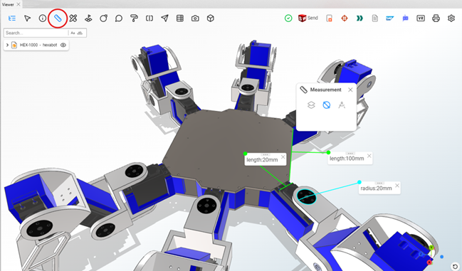
Measurement
The Measurement tool enables precise dimensional analysis with options for linear, angular, and edge measurements. It helps verify critical distances, angles, and other geometric properties.
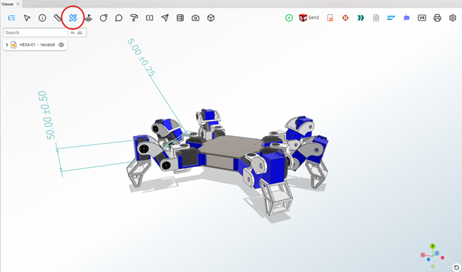
PMI (Product Manufacturing Information)
The Viewer supports PMI data, allowing you to view annotations such as tolerances, dimensions, and other manufacturing details directly within the 3D model.
Comments/Annotations
The Comments and Annotations tool allows users to add notes, highlights, and markups directly on the 3D model. These annotations are useful for collaborative reviews, communicating design changes or feedback, and reporting issues or errors. This feature helps streamline communication between team members, ensuring all stakeholders are aligned on the project’s progress and enabling quick identification and resolution of potential problems.
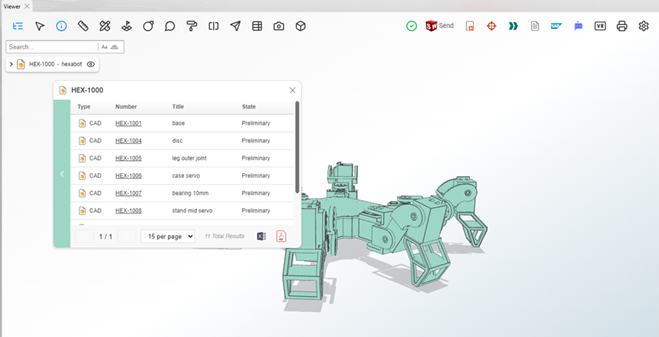
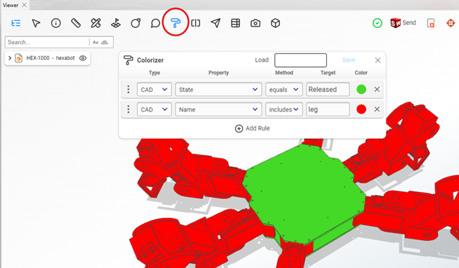
Colorizer
The Colorizer feature allows parts to be dynamically colored based on PLM data properties using custom rules. For example, parts in a “Released” state can be displayed in green, while “Preliminary” parts can be shown in red, providing clear visual cues.
Additionally, Colorizer rules can be diversified, making it easier to visualize multiple types of data on the model, enhancing the clarity and accessibility of complex information.
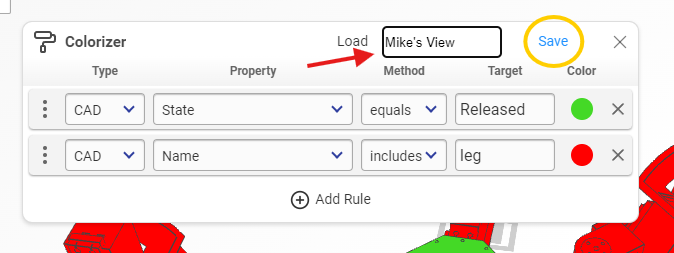
Defined rules can be saved for future use.
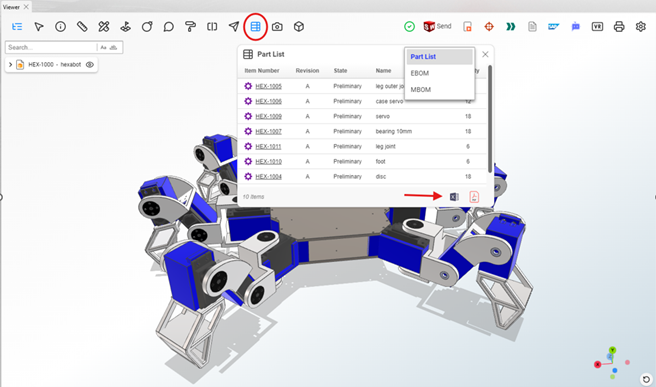
Part List
The Part List feature displays the assembly product tree with options to view EBOM (Engineering Bill of Materials) and MBOM (Manufacturing Bill of Materials) structures. The product tree can be exported in various formats, such as Excel or PDF, for external use.
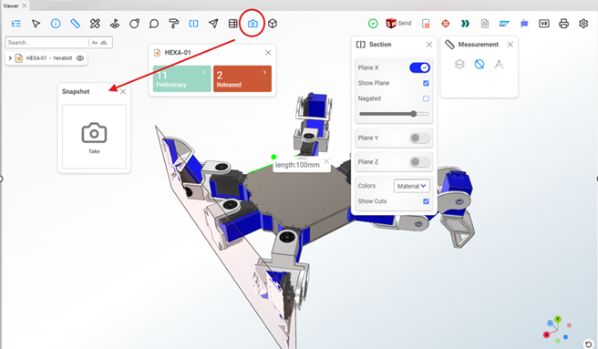
Snapshot
The Snapshot tool allows you to capture the Viewer screen, annotate it, and add notes or highlights. This feature is ideal for documenting and sharing specific views or details with stakeholders.
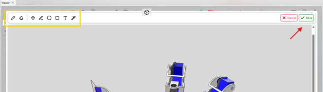
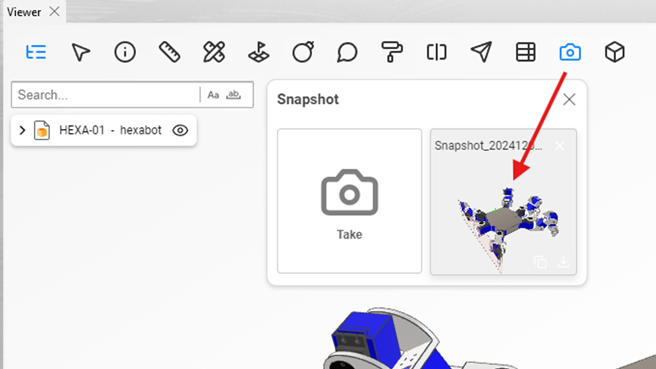
Once you click the Snapshot Take button, the snapshot automatically appears on the screen. The editor provides options to add or remove notes, insert shapes like squares and circles, add text, and customize colors. Additionally, the Save button allows you to store the snapshot in memory for future reference or sharing.
Display Style
The Display Style option in the DAIMIA Connector PLM Viewer offers several display modes to help users visualize the 3D model in different ways, depending on their preferences and needs:
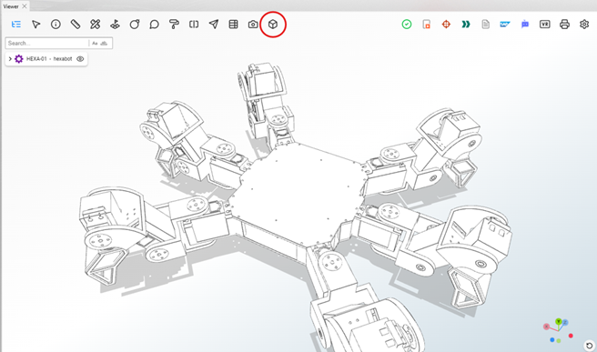
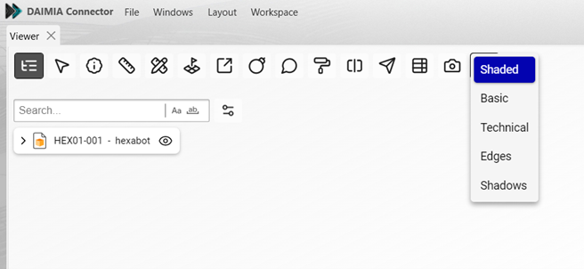
- Shaded: Displays the model with solid surfaces, providing a realistic view with colors and material shading.
- Basic: Shows a simplified version of the model without any advanced visual effects, focusing on the basic structure.
- Technical: Presents the model as a mesh of lines, highlighting the geometry and structure without solid surfaces.
- Edges: Emphasizes only the edges of the model, giving a clear outline view of the part or assembly.
- Shadows: Adds realistic shadows to the model, helping to visualize depth and spatial relationships between parts.
These modes allow users to choose the most appropriate visualization for their tasks, improving clarity and understanding of the model.